Masonry Wall Results
Masonry wall results are presented in the wall results spreadsheets and the detail reports. Results are reported on a region by region basis. In addition, the code checks for lintels spanning openings are reported separately.
For general wall panel information, see the Wall Panels topic. For information on masonry design rules, see the Masonry Wall - Design Rules . For masonry wall modeling procedures, see the Masonry Wall - Modeling topic. For masonry calculation considerations and code references, see the Masonry Wall - Design topic.
Spreadsheet Results
The information on this spreadsheet is present on
In Plane

Click on image to enlarge it
The In Plane results spreadsheet is intended to provide the code checks relevant to shear wall behavior for the wall.
Masonry Wall Spreadsheet - In Plane
|
Column |
Description |
|---|---|
|
Wall Panel |
The Wall Panel column displays the masonry wall panels defined in the model. |
|
Region |
The Region column lists the masonry wall panel region that the results are based on. |
|
Design Rule |
The Design Rule column displays the rule governing the design. |
|
Combined UC |
For ASD codes, the Combined UC column displays the code check due to axial force plus in-plane bending. |
|
LC |
The LC column adjacent to the Combined UC column, shows the individual code check for Combined UC. A value greater 1.0 for either of these values would indicate failure. |
|
Shear UC |
The Shear UC column shows the in-plane shear code check. A value greater than 1.0 for any of these values would indicate failure. |
|
LC |
The LC column adjacent to the Shear UC column, shows the load combination that produces each of the highest code check values. |
|
Fa (or Pn*Phi) |
The Fa or Pn*Phi column displays the allowable axial stress or axial capacity. |
|
Fb (or Mn*Phi) |
The Fb or Mn*Phi column displays the calculated allowable bending or moment capacity for the region. |
|
Fv (or Vn*Phi) |
The Fv or Vn*Phi column displays the calculated allowable shear stress or Shear Capacity for the region. |
Out of Plane

Click on image to enlarge it
The Out-of-Plane results spreadsheet is intended to provide the code checks relevant to out of plane bending for the wall.
Masonry Wall Spreadsheet - Out of Plane
|
Column |
Description |
|---|---|
|
Wall Panel |
The Wall Panel column displays the masonry wall panels defined in the model. |
|
Region |
The Region column lists the masonry wall panel region that the results are based on. |
|
Design Rule |
The Design Rule column displays the rule governing the design. |
|
Combined UC |
For ASD codes, the Combined UC column displays the code check due to axial force plus out of plane bending. A value greater than 1.0 would indicate failure. Note that this value represents the maximum of the different combined checks shown in the detail report ((fa+fb)/Fb, fa/Fa, and fs/Fs). |
|
LC |
The LC column adjacent to the Combined UC column, shows the individual code check for Combined UC. A value greater 1.0 for either of these values would indicate failure. |
|
Shear UC |
The Shear UC column shows the in-plane shear code check. A value greater than 1.0 for any of these values would indicate failure. |
|
LC |
The LC column adjacent to the Shear UC column, shows the load combination that produces each of the highest code check values. |
|
Fa (or Pn*Phi) |
The Fa or Pn*Phi column displays the allowable axial stress or axial capacity. |
|
Fb (or Mn*Phi) |
The Fb or Mn*Phi column displays the calculated allowable bending or moment capacity for the region. |
|
Fv (or Vn*Phi) |
The Fv or Vn*Phi column displays the calculated allowable shear stress for the region. |
For slender wall design additional checks and analyses are required. These are reported in the region's detail report.
Masonry Lintels

Click on image to enlarge it
The
Masonry Wall Spreadsheet - Lintel
|
Column |
Description |
|---|---|
|
Wall Panel |
The Wall Panel column displays the masonry wall panels defined in the model. |
|
Region |
The Region column lists the masonry wall panel region that the results are based on. |
|
Design Rule |
The Design Rule column displays the rule governing the design. |
|
Flexure UC |
The Flexure UC column displays the the code check due pure flexure of the Lintel. Axial force is not considered in this code check at all. |
|
LC |
The LC column adjacent to the Flexure UC column, shows the load combination that produces each of the highest code check values. |
|
Shear UC |
The Shear UC column displays the code check for shear. A value greater 1.0 for either of these values would indicate failure. |
|
LC |
The LC column adjacent to the Shear UC column, shows the load combination that produces each of the highest code check values. |
|
Fvm (or Vn*Phi) |
The Fvm or Vn*Phi column displays the allowable shear capacity. |
|
Fvs (or Vn*Phi) |
The Fvs or Vn*Phi column displays the allowable shear stress. |
|
Fm (or Mn*Phi) |
The Fm or Pn*Phi column displays the calculated allowable moment capacity for the region. |
|
Fs (or Mn*Phi) |
The Fs or Mn*Phi column displays the calculated allowable bending stress for the region. |
Reinforcing Spreadsheet Results
The last two tabs of this spreadsheet contain results for Masonry Wall reinforcement.
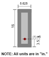
Masonry Wall
In Plane Masonry - Axial Details
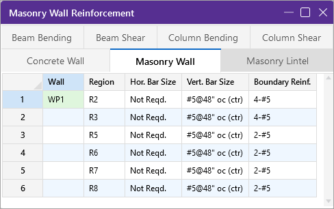
Click on image to enlarge it
The Masonry Wall spreadsheet displays analysis results for the reinforcement of each region defined in your masonry wall.
Lintel Reinforcing
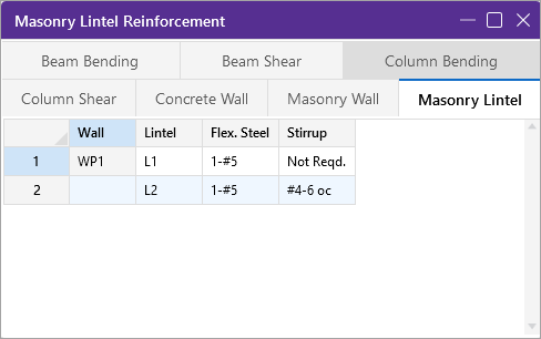
The
Masonry Wall Detail Report
The detail reports show the overall geometry, analysis and design for the individual regions of the wall panel. The report also shows envelope diagrams for the forces and moments in the region.
Three basic types of detail reports are provided: Wall Summary, Region and Opening.
Accessing the Detail Reports and the Specific Windows
Once you have a solved model, the detail reports become available. They are accessible in two ways:
- If you have the
 . This opens the detail report window.
 - If you are in a graphic view of your model, there is a
 button on the Selection toolbar. Clicking this button and clicking on a wall panel will open up the detail report window for that wall panel.
Once the detail report window is open, you see an area at the top.

Click on image to enlarge it
The following table describes the options that control the display of the Detail Report.
Detail Report Control Options
| Option | Name | Description |
|---|---|---|
|
|
Prior/Next |
The left and right arrows let you scroll quickly between the different wall panels in your model. |
|
|
Wall Panel Part |
The first drop-down list lets you choose between individual Region and Opening (Lintel) results and a summary of the entire Wall. |
|
|
Regions/Headers |
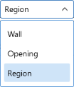
The second drop-down list lets you select between different Regions or Openings within the individual wall panel. “R” represents regions, while “L” represents levels (headers). The is available only when ‘Opening’ or ‘Region’ is chosen in the Wall Panel Part drop-down. |
|
|
In/Out Plane |
If you have selected a Region, then you have the option of whether to view the in plane or out of plane report. The is available only when ‘Region’ is chosen in the Wall Panel Part drop-down. |
|
The following options can be found at the bottom of the Detail Report window. |
||
|
|
|
Lets you print the Detail Report. |
|
|
Add to Full Report |
Lets you add the current detail report you are viewing to the printed report. View the Printing topic for more information. |

 or
or 


Detail Report - Wall Summary
This report gives an overview of the wall, a summary of the controlling code checks and deflection information. This report also displays information about the wall, similar to the Region Input Echo and also gives an image of the wall. The image shows region locations, wall length and story dimensions, and the nodes that define the corners of the wall panel.

Click on image to enlarge it
The Region Results section gives the tabulated results of all regions in the wall for in plane design axial/bending, shear and deflection for quick reference. You can view the individual region reports to get a more detailed explanation of these values.
The Reinforcement Results section gives the reinforcement results for each region in the wall.
The Lintel Reinforcement Resultssection gives the label and reinforcement for any lintels in the wall.
Detail Report - In Plane
In Plane-Masonry - Input Echo
The top section of the detail report echoes back the input information used in the design of the wall region or lintel. This information is summarized below:

Click on image to enlarge it
Detail Report - Criteria Column
|
Criteria |
Description |
|---|---|
|
Code |
Gives the code used to design your wall panel. |
|
Special Inspection |
Indicates whether special inspection is required for your wall. Special inspection is normally required for all walls designed to the MSJC / IBC codes. The UBC 1997 is the one code that allows the user to decide whether special inspection is required. |
|
Wall Area |
See the Wall Design Rules - Masonry Wall spreadsheet |
|
Horizontal Bar Size |
Indicates the bar size to be used to resist shear forces. |
|
Vertical Bar Size |
Indicates the bar size to be used to resist the tensile stress due to moment. |
|
Number of Tension Bars |
Indicates the number of vertical bars present in the boundary region of the wall. |
|
Effective depth |
This gives you the distance from the compression face of the wall to the centroid of tension reinforcement. |
The Geometry column gives the basic geometry of the wall. Block grouting and the grout spacing are specified in the Wall Panel Editor. The block nominal width is input under the Wall Design Rules - Masonry Wall tab.
The Materials column can be mostly modified under the Materials button on the Data Entry toolbar.
The Envelope Diagrams section of the detail report displays the envelope axial shear and moment diagrams as well as a summary of the code checks performed on the shear wall.

Click on image to enlarge it
The Combined Check Summary gives maximum overall code checks considering the effects of both bending and axial stresses. This section is not reported for MSJC strength design.
The Axial Summary and Bending Summary give the values used in the axial and flexural code checks at the location which controls the combined check (fa+fb)/Fb for ASD design.
For ASD design, the maximum bending stress in the flexural reinforcement is reported as fs, and the allowable steel bending stress as Fs. These values are given for the Load Combination and section that produce the maximum code check (fs/Fs).
The Shear Summary reports the maximum shear demand on the beam as fv or Vu. The allowable shear stresses are then reported as Fvm and Fvs, where Fvm is the allowable of the masonry alone and Fvs is the allowable considering the effects of the shear reinforcement.

Click on image to enlarge it
Detail Report - Axial Details
|
Axial Details |
Description |
|---|---|
|
Maximum Axial Force |
The maximum axial force in the wall. |
|
Location |
The location along the height of the wall which produces the maximum axial force. |
|
Load Combination |
The load combination that produced the maximum axial force. |
|
Radius of Gyration (r) |
The out of plane radius of gyration for the wall. |
|
h/r |
Slenderness ratio of the wall |
|
Reduction Factor R
|
This is the slenderness reduction portion of equations 8-11, 8-12, 9-9and 9-10. |
In Plane Masonry - Bending Details
|
Working Stress Design (ASD) |
|
Click on image to enlarge it |
|
|
|
Ultimate Strength Design |
|
Click on image to enlarge it |


Detail Report - Bending Details
|
Bending Details |
Description |
|---|---|
|
Maximum Moment |
The maximum moment in the wall. |
|
Location |
The height of the wall where the maximum bending moment is located. |
|
Load Combination |
The load combination that produced the maximum bending moment. |
|
Section Modulus (S) |
The uncracked section modulus. This is based on the effective thickness and the length of the wall. |
|
Tension Steel Asv |
The area of tension steel in this region of the wall panel. |
|
Percentage of Steel (p) |
The reinforcement ratio in this region of the wall panel. |
|
k*d |
The length of the compression block. |
|
j |
The ratio of the distance between the centroid of the compressive and tensile forces (j). |
|
a |
Depth of compression block. |
|
c |
Depth of Neutral Axis. |
|
d |
Depth of section from compression fiber to centroid of tensile reinforcement. |
In Plane Masonry - Cracked Section Details
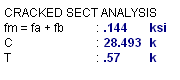
See the Masonry Wall - Design topic for more information.
In Plane Masonry - Shear Details
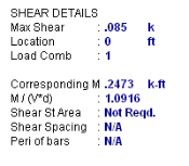
Detail Report - Shear Details
|
Shear Details |
Description |
|---|---|
|
Moment |
The moment corresponding to the maximum shear check is reported along with the M/Vd ratio. |
|
Shear Bar Spacing |
The spacing of shear steel in the region of the wall panel. |
|
Perimeter of Bars |
Used in the bond stress checks for ASD design. |
This section of the detail report is meant to provide a visual confirmation to the user of the boundary zone width and reinforcement.
Detail Report - Out of Plane
Out of Plane Walls - Input Echo
The top section of the detail report echoes back the input information used in the design of the wall region or lintel. This information is summarized below:

Click on image to enlarge it
The information in the Criteria section is mostly described in detail in the section on In Plane Detail Report. The End Face Dist is the distance from the edge of wall to centroid of vertical bar.
The Materials column can be mostly modified under the Materials button on the Data Entry toolbar.
The Geometry column gives the basic geometry of the wall. Block grouting and the grout spacing are specified in the Wall Panel Editor. The block nominal width is input under the Design Rules>Masonry wall tab.
The Eq Solid Thickness comes from the "Wall Area Method" in the Wall Design Rules - Masonry Wall tab.
Out of Plane Walls - Force Diagrams and Code Summary (ASD)
The next section of the detail report displays the envelope axial shear and moment diagrams as well as a summary of the code checks performed on the transverse wall.

Click on image to enlarge it
TheCombined Check Summary gives maximum overall code checks considering the effects of both bending and axial stresses. This section is not reported for MSJC strength design.
TheAxial Summary and Bending Summary give the values used in the axial and flexural code checks at the location which controls the combined check (fa/Fa)+(fb/Fb).
For ASD design, the maximum bending stress in the flexural reinforcement is reported as fs, and the allowable steel bending stress as Fs. These values are given for the Load Combination and section that produce the maximum code check (fs/Fs).
The Shear Summary reports the maximum shear demand on the beam as fv or Vu. The allowable shear stresses are then reported as Fv.

Click on image to enlarge it
Detail Report - Design Details
|
Design Details |
Description |
|---|---|
|
Radius of Gyration (r) |
The out of plane radius of gyration for the wall. |
|
h/r |
Slenderness ratio of the wall. |
|
k |
This value multiplied by d gives the depth to the neutral axis. |
|
d |
The depth between the extreme face of masonry in compression and the center of the tension reinf. |
|
j |
This value multiplied by d gives the moment arm between the compression and tension resultants. |
|
Width for Shear |
This is the value used to calculate the shear capacity. For fully-grouted walls, this is simply the center to center spacing of vertical reinforcement. For partially-grouted walls, this value is conservatively taken as the width of the grouted cell plus the thickness of the web and end wall on either side. An example of this can be seen in Example 6.3 (p6.65) of "Design of Reinforced Masonry Structures" by Taly, copyright 2001. |
|
Corresponding M & P |
These are the moments and axial forces used to calculate the shear capacity. These are both conservatively taken as the maximum M & P in the entire region, rather than the M & P at the location of maximum shear. |
|
M/(V*d) |
This is the M/Vd ratio used to calculate the shear capacity. |
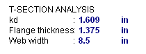
T-Section Analysis
See the Masonry Wall - Design topic for information on a T-section analysis.
Detail Report - Out of Plane Slender
Out of Plane Walls - Force Diagrams and Code Summary (Strength)
The next section of the detail report displays the envelope axial shear and moment diagrams as well as a summary of the code checks performed on the out-of-plane loaded slender wall.
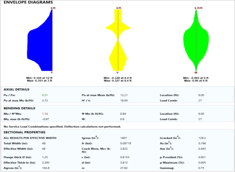
Click on image to enlarge it
TheAxial Detailsprovide the axial code check for pure compression forces. The Pn at max Mom value reported is the maximum allowable axial force based on Section 9.3.5.4.2
TheBending Detailsare explained below:
- Mu/ phi*Mn represents the ratio of applied moment to moment capacity of the wall
- Mu, max is the out-of-plane bending moment at the controlling location of the wall.
- phi Mn is the out-of-plane moment capacity of the wall at the controlling location. It is calculated per Section 9.3.5.2.
- phi is the strength reduction factor specified in Section 9.1.4.
- Location is the elevation of the wall which resulted in the highest (Mu / phi*Mn) ratio. It is the location at which Mu and Pu are used to calculate phi Mn.
- Load Combination is the load combination which resulted in an Mu and Pu which yielded the highest (Mu / phi*Mn) ratio.
If there is an over-reinforced section this can cause a failure in the masonry wall solver. If this occurs the program will produce an Over-reinforced message. To reconcile this you will need to either increase the thickness of masonry block, decrease the grout spacing or decrease the bar size or number of bars in the wall.

Click on image to enlarge it
Deflection Details
Dmax/Dlimit is a code check result. Thus, if the value is larger than one, your wall fails deflection criteria. Dmax (Δmax) is the calculated deflecting using the iterative slender wall design procedure detailed in the Masonry Wall - Design topic. The Dlimit (Deflection Limit) is the allowable deflection from TMS 402-13 Section 9.3.5.5.
- Both the Service and the Masonry flags must be checked on the Design tab of the Load Combinations for the deflections to be checked for that load combination.
- The forces in the region are given on a per foot basis and are an average of the forces over the width of the region.
Sectional Properties (Strength)

Click on image to enlarge it
The center to center distance between reinforcing Total Width and the Eff Width (which accounts for partially grouted walls) are both reported in this section. The Flange Thick tf refers to the thickness of the face shell whereas the Effective Thick te refers to the overall effective depth of the block.
The gross area and moment of inertia are reported along with the modulus of rupture, cracking moment, neutral axis, modular ratio between steel and masonry, and the cracked moment of inertia.
The area of steel As and the effective area of steel Ase are reported, with the effective area based upon As + Pu/fy.
The gross steel ratio (rho gross) is calculated as the area of steel divided by the total area of the section.
The Rho Provided (%) is calculated as the area of steel divided by the total width times the effective depth (As/bd). This is limited to a Rho Maximum (%) value of 0.5 * rho balanced per the UBC-97 Section 2108.2.3.7. This provision was implemented in future codes as well.
The Sectional Properties gives a number of the properties used during the iterative slender wall design procedure. All of these properties are reported based on a section of wall equal to the center to center spacing of the reinforcement.
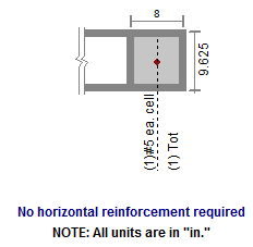
Out of Plane Masonry - Cross Section Detailing
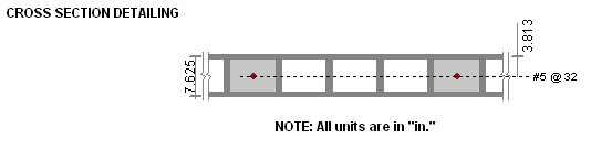
This section of the detail report is meant to provide a visual confirmation to the user of the spacing and location of reinforcement.
Detail Report - Lintels
Lintels - Criteria / Materials / Geometry
The first section of the detail report echoes back the basic input parameters (Criteria, Materials, Geometry) entered by the user. An example is shown below:
The geometry portion and the dead weight of the wall warrant further explanation.
Detail Report - Lintels
|
Attribute |
Description |
|---|---|
|
Dist to Top of Wall |
This is the distance from the top of the lintel to the top of the wall and is used in the calculation of the arching action of the lintel loads. |
|
Actual Length |
This is the total width of the opening. |
|
Bearing Length |
This is the bearing length of the lintel on either side of the opening. |
|
Effective Length |
The Center to Center distance between lintel supports. Assumed to be length of the opening plus half of the bearing area on each side. |
|
Effective Width |
The thickness of the block used to define the lintel. |
|
Effective depth |
Equivalent to the "d" distance, the distance from the effective compression face to the centerline of the tension reinforcing. |
|
Total Depth |
This is the total depth of the fully grouted portion of the lintel. |
|
Beam Dead Weight |
This is based on the user defined density for the Lintel / Opening. |
|
Wall Dead Weight |
This is based on the wall self weight or the self weight of the region immediately above the opening. |
Lintel Detail Reports - Diagrams and Code Check Summary
The next section of the detail report provides the envelope shear and moment diagrams as well as a summary of the code checks for the Lintel.

Click on image to enlarge it
Lintel Detail Reports - Design Details
The next section of the detail report gives further details for the design checks performed on the lintel.

Click on image to enlarge it
This Bending Details show the magnitude, location and load combination that correspond to the maximum moment used in the design as well as the area of flexural steel required (As) and the steel ratio (rho).
The Compressive Stress Block Details show the parameters used in calculating the strength of the lintel.
The Shear Details show the magnitude, location and load combination that correspond to the maximum shear used in the design, the M/(V*d) ratio for shear design, and the required spacing of ties (if applicable).
Lintel Detail Reports - Cross Section Detailing
This section of the detail report is meant to provide a visual confirmation to the user of the basic geometry and reinforcement provided in the lintel.